Weld Analysis with Ansys
Figure 1: Equivalent Stress of White Paper Model
There are many software out there now that does weld analysis. Among others...
- For fatigue type analysis, there are: FE-Safe (Verity Method) & Ncode (Volvo Method)
- For static type analysis, there are: FEWeld & EDRMedeso
A good reference classic book is Blodgett's Design of Welded Structures (1966). This book is a real gem even though it's quite old. Here is a short write-up by the same author et al with similar material: Welded Connections.
White Paper
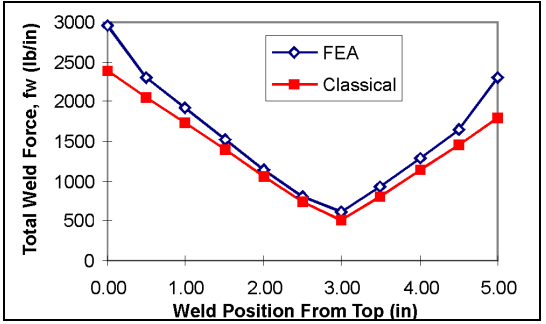
Figure 2: Weaver's White Paper Comparing FEA to Hand Calculations
I came across this really good white paper by Weaver Engineering that had a worked example comparing both hand calculation to their software along with in depth discussions. The example was detailed enough to be replicated. This is a great stepping stone when following the crawl-walk-run philosophy.
The rest of the post seeks to replicate the results in the white paper.
Model and Snippet Comments
A critical step in setting up the model is highlighted in Figure 3. Nodal Forces has to be computed for later post processing and "Save MAPDL db" is required for later named selection pointing. This should be done before the model is solved.
Secondly, the forces at the weld-line was extracted with the elements of the terminating member selected. As noted in the FSUM help document: "Sums and prints, in each component direction for the total selected node set, the nodal force and moment contributions of the selected elements attached to the node set." To find the "effective length" of the weld associated with the extracted load, the average length was taken (see script for details).
Finally, the Workbench model takes advantage of Ansys DesignXplorer with Snippets similar to a previous post to test the sensitivity of mesh size.
Results
In Figure 2 by Weaver, his peak weld force/length (fw) from hand calculation comes in at 2,390lbf/in. In this Ansys Model and associated script, it peaked at 2,775lbf/in for 10 elements along the weld line (WELDFORCE10.txt). As the number of elements is increased, so too did the force/length. It appears to be a singularity there though the good news is that if one is to use the "hot spot method", the trend is slightly under 3,000lbf/in which is in line with the White Paper's FEA model.
A better way of averaging out the forces at the end could be finessed if needed. All the best!
Source Files
Model and Snippet Comments
A critical step in setting up the model is highlighted in Figure 3. Nodal Forces has to be computed for later post processing and "Save MAPDL db" is required for later named selection pointing. This should be done before the model is solved.
Figure 3: Key Settings
Secondly, the forces at the weld-line was extracted with the elements of the terminating member selected. As noted in the FSUM help document: "Sums and prints, in each component direction for the total selected node set, the nodal force and moment contributions of the selected elements attached to the node set." To find the "effective length" of the weld associated with the extracted load, the average length was taken (see script for details).
Finally, the Workbench model takes advantage of Ansys DesignXplorer with Snippets similar to a previous post to test the sensitivity of mesh size.
Results
Figure 4: Ansys Results with Different Mesh Density
In Figure 2 by Weaver, his peak weld force/length (fw) from hand calculation comes in at 2,390lbf/in. In this Ansys Model and associated script, it peaked at 2,775lbf/in for 10 elements along the weld line (WELDFORCE10.txt). As the number of elements is increased, so too did the force/length. It appears to be a singularity there though the good news is that if one is to use the "hot spot method", the trend is slightly under 3,000lbf/in which is in line with the White Paper's FEA model.
A better way of averaging out the forces at the end could be finessed if needed. All the best!
Source Files


thanks for this information
ReplyDelete